|
|
Post by Armageddous on Apr 3, 2015 11:09:39 GMT -5
At one point, there was a talented individual on this forum who had discussed a way of making an adjustable cam gear. I can't seem to find that thread, what say the community?
I have the tooling (drill press, lathe, stubbornness), but I would like some input as to the best way to approach it, as the 3 hole center makes it a little complicated. I was thinking of making a ring that overlaps the pre-drilled holes that also centers the inner and outer sections of the gear (once it's been cut to allow the change in timing). A protractor or computer/printer could be used to make the degree notches.
This comes as inspiration after taking a course (2 years ago..) thru my work about variable cams, their operation and their effect on an engine. _Most_ OE configurations from the 80's and 90's have the cams set up to benefit economy and emissions by aiding the catalytic converter. Remove the cat, change the engine, the cam timing needs to be changed (Also the profile, but 1 step at a time).
Anyways, who's on board?
Terry
|
|
|
|
Post by certimafied on Apr 3, 2015 11:45:46 GMT -5
Are you talking about a vvt kind of set up or a cam cog that would allow you to degree the cam to be as efficient as possible. I've got and idea for the latter of the two.
What if you were to get rid of the three mounting bolts, and you tap the center of the cam so that you can screw in a stout bolt to hold the cog. Now you take the cog and drill a series of holes going around that would line up with the roller pin that is already in place. Then once you have your cam where you want it in relationship to the crank you can slide the cog on how ever you can and use the big center bolt to lock everything together.
The italian cars I work on use a setup like this, though I dont feel that I explained myself well. The hard part in what I just said is knowing exactly where your cam is clocked in and how do you hold it there while you attach the cog and timing belt. and that the only thing holding your cam in time would be the clamping force of the center bolt and that little roller pin.
Theres my two cents and my lunch break is over, I'm going to think about this more though Im intrigued.
|
|
|
|
Post by Armageddous on Apr 3, 2015 12:34:10 GMT -5
Not, not a variable setup. There is no use on a single cam engine unless you move it a great amount.
Are you proposing the centering dowel on the cam should fit in to drilled holes on the cam gear? Given the size of the dowel and the relatively small area in which you have to work with, I think your adjustment would not be fine enough. We're talking 10deg or less.
If you are suggesting the dowel hole be extended to allow turning, the cam gear would move a lot by itself and either come loose or over-tighten and break the center bolt.
Tho if it did work that would be a really easy way to do it!
Terry
|
|
|
|
Post by certimafied on Apr 3, 2015 14:41:57 GMT -5
If you are suggesting the dowel hole be extended to allow turning, the cam gear would move a lot by itself and either come loose or over-tighten and break the center bolt. Tho if it did work that would be a really easy way to do it! Terry Im saying where the dowel is now what if you drilled holes beside the existing hole that would allow you to rotate the cam gear over to the right or left a 'hole' to gain more or less advance in the cam shaft compared to the cranks shaft. Have that with a big bolt in the center to 'lock' it. that way you can essentially get more degree out of the cam. It sounds good in my head. |
|
|
|
Post by certimafied on Apr 3, 2015 14:52:30 GMT -5
there would actually have to be a series of holes in the camshaft and in the cam gear itself for that to work with a removable dowel. That way once you put the cam where you want it you can put the gear up to it put the timing belt on tension it and then slide the dowel pin in to lock it in time and then the center bolt would thread in and hold everything together. Of course the holes wouldnt line up that easily but that is the idea and that is how its done on a 308/328. I'm trying to find a picture of what I'm talking about to post no luck at the moment.
I think it is possible without much modification or even money, time would be the big thing.
|
|
|
|
Post by certimafied on Apr 3, 2015 20:19:30 GMT -5
|
|
|
|
Post by Armageddous on Apr 3, 2015 20:33:48 GMT -5
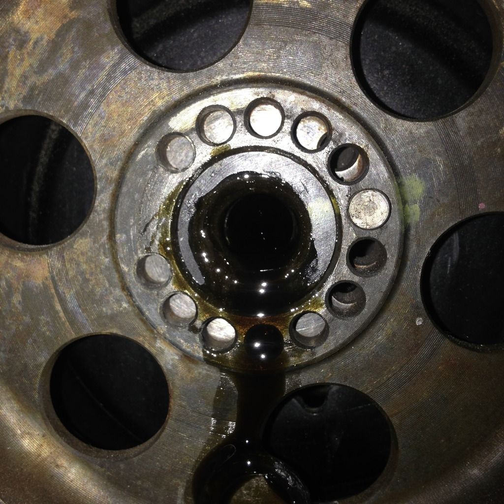
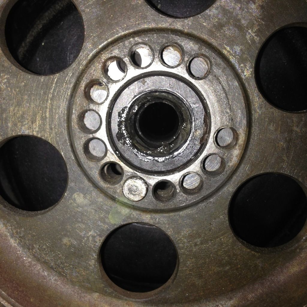
Just as you were posting that, I was working the numbers. The circumference draw for the radius of the dowel is approx 80mm, the dowel is approx 5mm. Spaced perfectly together you can fit 17 dowels along that circumference. This gives ~21degrees per hole.. Which sucks. And that is of course assuming you could drill that accurately (which you can't).
Now from those pictures it looks like to remedy this inaccuracy they opted to drill other dowel holes which are (likely) spaced at divisions in degrees of the first, which depending on the dowel will increase the accuracy.
For example..
Dowel #1 21 deg from TDC
Dowel #2 11 deg from TDC
Dowel #3 6 deg from TDC
Yet each dowel hole in the cam by itself it still limited to a 21 deg separation dictated by the cam gear.
So each dowel is really just a dowel of a finite adjustment.
Terry
|
|
|
|
Post by Armageddous on Apr 3, 2015 20:51:28 GMT -5
Here goes my attempt to explain something. 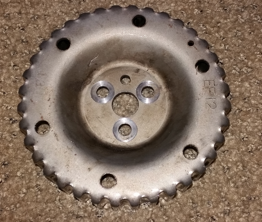 My idea was, to cut the gear along the step (where it tapers) along the high side where it flattens out, while still leaving the 6 holes in tact. (Are they speed holes or what?) Tap the holes to the closest matching thread and insert bolts facing outward. Then fabricate a ring that is welded to the inner section (the part that mounts to the cam) that has 4 or 6 slotted holes alongthe outside edge that line up with the factory holes (with bolts) in the gear, where the center of the slot means the cam is at TDC. Use nuts to secure them together. Have an angle indicator to show left retarded and right advanced, and the number (IE -15......0 TDC......15) Terry |
|
|
|
Post by gearheadeh on Apr 3, 2015 21:24:51 GMT -5
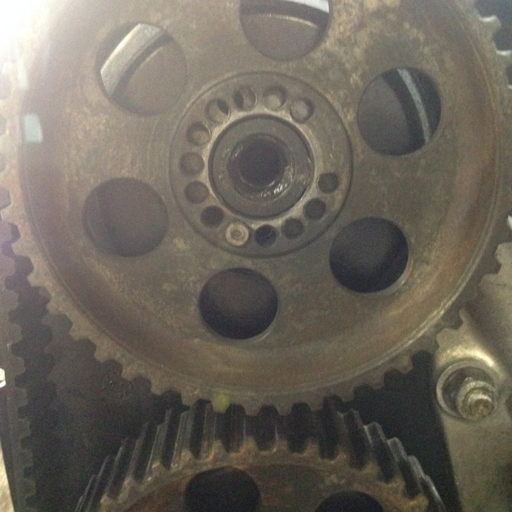
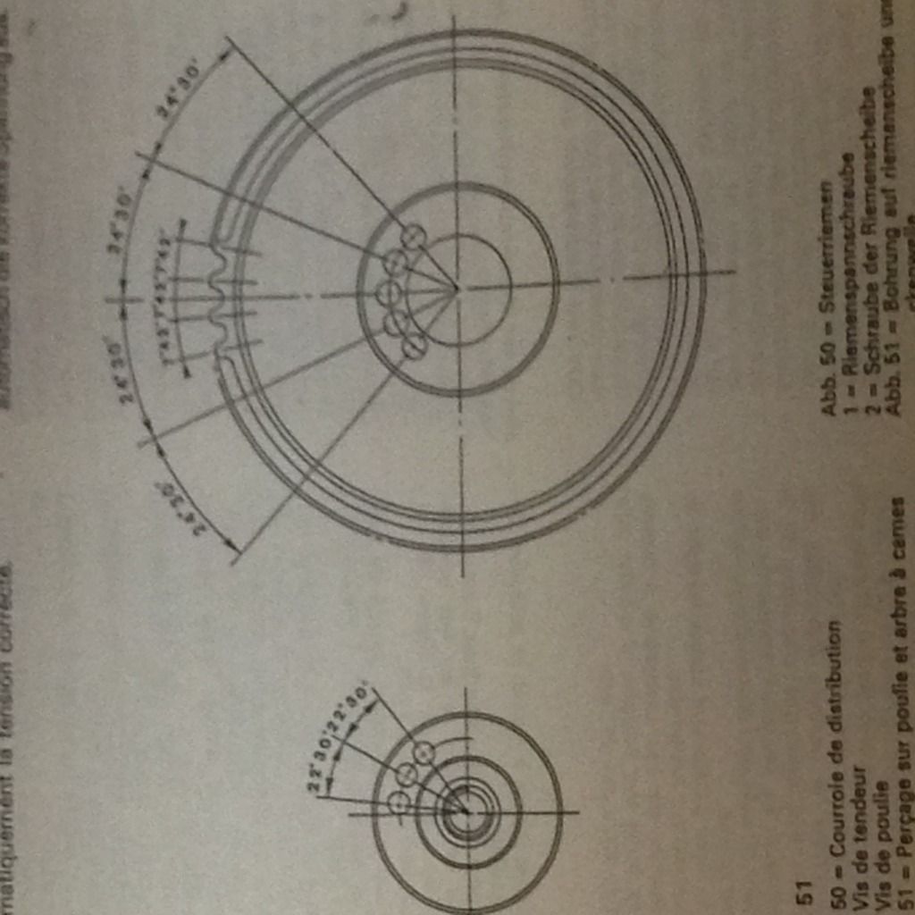
Warning: I don't think you can depend on those holes being drilled true and concentric to each other! Picture depicts degrees of rotation between each hole in succession. 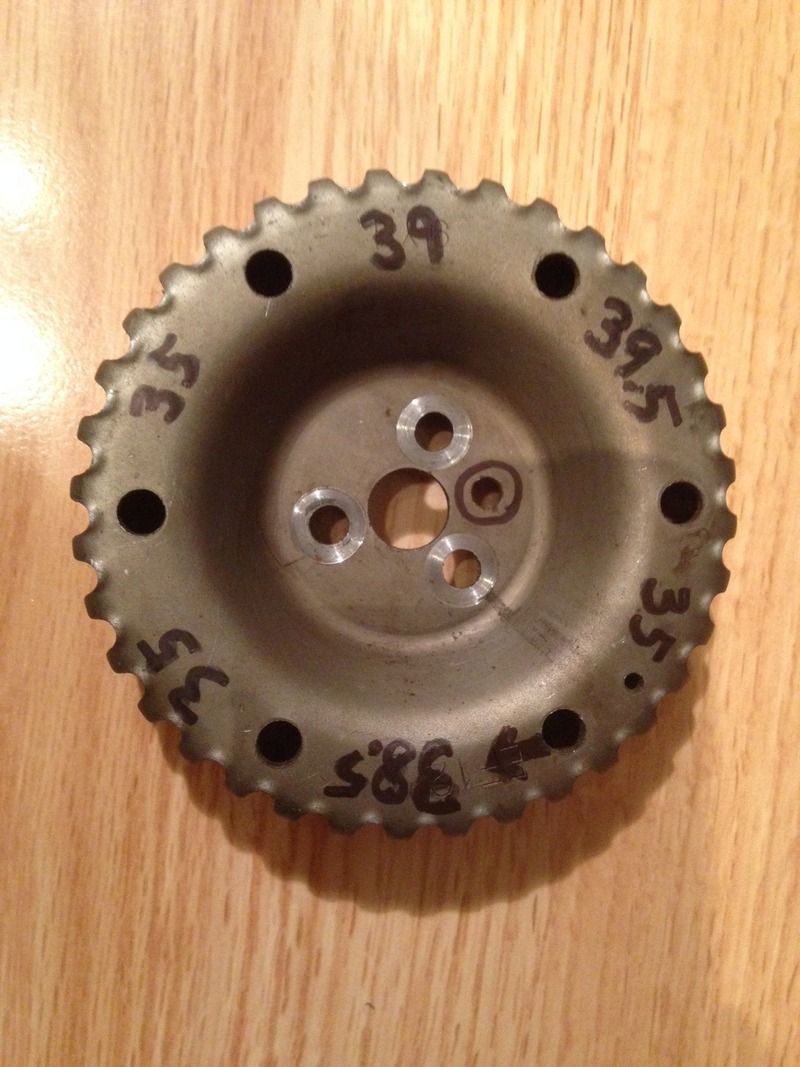 |
|
|
|
Post by Armageddous on Apr 3, 2015 22:08:42 GMT -5
Interesting. Here I would have assumed contrary and ended up finding out when I went to put it together.
I just measured the distance between them and they are indeed different, although it is symmetrical when measured with a caliper.
If we call the hole nearest the alignment hold #1 and count clockwise, the distances between them (measured from outside of the hole to the outside of the adjacent). We find:
1 to 2 and 4 to 5 match,
and
2 to 3 and 5 to 6 match.
Terry
|
|
|
|
Post by madmatt on Apr 19, 2015 0:05:04 GMT -5
omg...
how did i miss this thread...
i spent many long nights looking at rhe cam wheel, and came up with some clocking conclusions when i millled the 1.4 mm off the head... i wrote them down somewhere... but umm I'm bad at keeping that stuff. i realized i couldn't get back in time with clocking on the stock bolt holes... but there was +- 10 degree gains to made...
I'm working on mounting the oil pump gear to the cam gear... using those symmetrical but messed holes in the wheel... threw me for a loop when i couldn't get the plate to mate up...
I've had thoughts of being able to adjust the timing through that. hmmmm I'll think harder.
|
|
|
|
Post by Mato393 on Oct 5, 2016 11:29:20 GMT -5
I'm just 3D printing this EJ20 engine model and today I get the timing belt for it... When I put it on the printed cam gear and i was like "Damn! That fits nice!" then that thread cames up on my mind... Yes, some stupid plastic won't work. BUT! There is this thing: markforged.com/mark-two This can print a nylon part with carbon fibre (or kevlar and glass fiber) inside! It should be strong as alluminium and I think it will be lighter than that steel one. I trust that technology a lot but I'm not sure about putting it in engine... |
|
|
|
Post by madmatt on Oct 7, 2016 20:50:38 GMT -5
I have this all figured out... I JUST NEED A LATHE... been searching, missed a few, have nothing to spend... if you have an old altas, southbend, or even a King...  I'm looking. |
|


 I'm looking.
 Is your car an ecvt?